The Data Sheet That Gets You a Real Answer: Eight Numbers and Why Each One Matters
Eight numbers decide a steam-saving design. Why each one changes the answer: motive and delivery pressure, minimum and maximum flow, flash pressure, feed limits, fuel basis, hours and meters.
On this page
- 1. Motive pressure at the jet, under load
- 2. The temperature the process needs, not the header set point
- 3. Minimum and maximum flow at every pressure-reducing station
- 4. Where the condensate drains, and where the flash goes
- 5. The feed tank temperature, and what limits it
- 6. Steam raised and fuel burnt, on one stated heat value
- 7. The hours, and the load during those hours
- 8. Which meters you already have
- What good numbers do
- What we need from you
A steam-saving design can be engineered perfectly on a wrong number: a pressure taken from a nameplate, a flow that was really an average, a feed tank that could never take the heat it was promised. The data sheet decides the design long before anyone draws it.
Our post on seven things we look at before we open a drawing lists what to read on a plant. This one goes a step further: eight numbers, why each one changes the answer, and what happens to the design when one of them is wrong. The examples come from the steam tables and from past audits and proposals, with the names taken off.
1. Motive pressure at the jet, under load
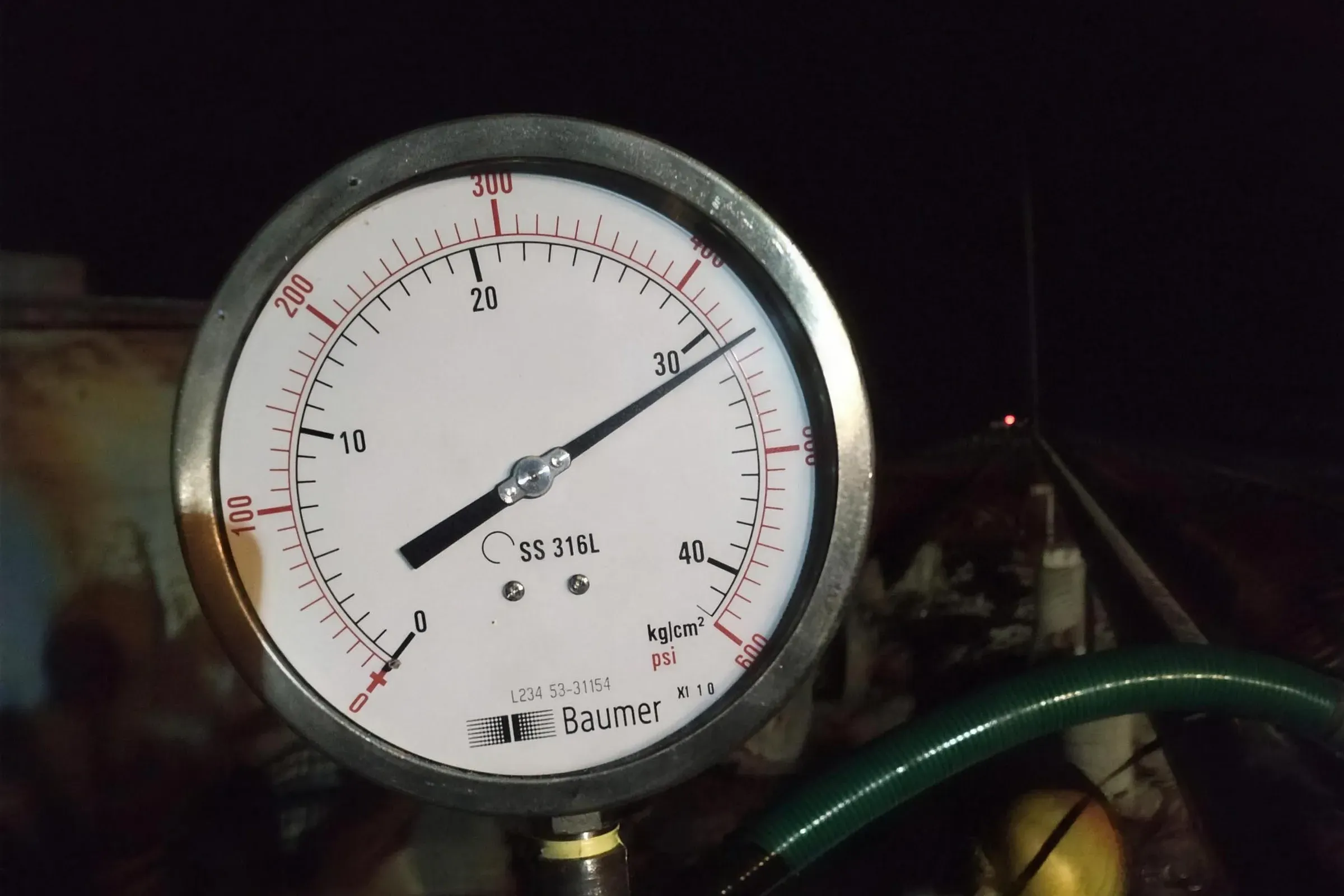
A Jetomat uses high-pressure steam to lift low-pressure steam. The gap between motive and delivery pressure sets how much it can lift. The number that counts is the pressure at the jet’s inlet while the plant is running, not the boiler nameplate.
One boiler with an on-off burner was set to cut in at 8 and out at 10 bar g, and it swung through that band all day. Anything fed from it has to be designed on the bottom of the band. A design on the top of it comes up short every time the burner cuts in.
2. The temperature the process needs, not the header set point
Delivery pressure follows from temperature. Saturated steam at 3.5 bar g is at 148 °C; at 2.5 bar g it is at 139 °C. If a dryer needs 139 °C but the sheet says 3.5 bar g because that is what the header runs at, the jet is asked to make a full bar more than the process needs, and it lifts less low-pressure steam to do it. Send the temperature the product needs and the pressure the header runs at. The design finds the gap.
3. Minimum and maximum flow at every pressure-reducing station
Pressures alone size nothing. Flow does, at both ends. One pre-proposal questionnaire from a past audit asked for inlet and outlet pressure and pipe size at each pressure-reducing station, and no flow. Its own review noted that a valve cannot be checked for size or velocity without flow, and added minimum and maximum flow in kg/h.
Both ends matter because loads move. On one corrugator reference machine, a single DN65 Jetomat modulates its motive flow from 400 to 1,500 kg/h, a 3.75 to 1 turndown on one actuated spindle. A variable nozzle can follow that, but only if the design knows where the bottom and the top are. A design on the average alone is too big at low load and too small at start-up.
4. Where the condensate drains, and where the flash goes
Flash depends on two pressures: the one at the trap, and the one the flash is sent to. From the steam tables, condensate at 7 bar g flashes about 13.4 % when it drops to atmosphere. Sent into a 3.5 bar g header, it flashes about 4.6 %. Same condensate, nearly three times the flash, decided by one line of the data sheet.
Measured flash can be lower still. One audit worked out 168 kg/h on paper, measured 60 to 100 kg/h, and sized the separator on the measured 60. The infrared check in how to check a steam-saving proposal shows how to read the trap pressure from the pipe.
5. The feed tank temperature, and what limits it
Recovered heat that ends up in the feed tank is capped by what the feed system can take. At one plant the feed pumps were rated only to 70 °C, with no deaerator head. At another, the boiler maker limited the economiser inlet to 60 °C, which capped condensate return at about a quarter of the steam generated.
A data sheet that leaves these out gets a recovery scheme the boiler house cannot accept without new pumps or a pressurised feed tank. Send the feed tank temperature, whether it is vented, and the pump and economiser limits.
6. Steam raised and fuel burnt, on one stated heat value
Every saving is turned into fuel at the end, so the fuel basis has to be written down: which fuel, its heat value, gross or net, and the boiler efficiency. One validation document used one heat value and efficiency in its blowdown sheet and a different pair in its stated basis. For the same heat, the two gave fuel savings about 20 % apart. Pick one basis, say which it is, and use it throughout.
7. The hours, and the load during those hours
A saving in kg/h becomes a saving a year through hours. One proposal used 7,200 hours a year on one page and 8,400 on another: the same equipment, a saving 17 % different. Hours also need a load beside them, so send days a year, shifts a day, and what the load does on each shift.
8. Which meters you already have
The last number decides whether anyone can prove the result: which fuel, steam and water meters exist, where they sit, and whether they are trusted. A proposal that knows the meters can name its measurement before installation. One that does not ends up judged on the fuel bill, where production, weather and every other project on site blur the answer.
What good numbers do
The Bharuch chemical plant shows the numbers doing the work. Motive steam at 16.5 bar, delivery at 3.5 bar, and a flash volume that varied with the heating loads: those three chose a variable-nozzle Jetomat, tied in parallel with the existing pressure-reducing station. It saves 422 kg/h of steam, the plant’s own figure, published by CII (case study). The lesson on the steam balance shows how to put all the flows on one drawing.
What we need from you
- Motive steam pressure at the point of use, at low and at high load.
- The temperature each process needs, and the pressure its header runs at.
- Minimum and maximum flow at each pressure-reducing station, in kg/h.
- Trap pressures, and where condensate and flash go today.
- Feed tank temperature, vented or pressurised, and the feed pump and economiser limits.
- Fuel and its heat value (gross or net), operating hours, and the meters you have.
FAQ
Why does the minimum flow matter if equipment is sized on the peak?
Because the equipment has to work at both ends. A unit designed only for the peak runs nearly closed at low load. A variable nozzle follows the load between the two, but the design needs both figures.
Can I just send the boiler's nameplate pressure?
Send it, and also the pressure at the point of use when the plant is loaded. A boiler that swings between its cut-in and cut-out pressures has to be designed on the bottom of the band.
What if I do not know my flows?
Send what you have: fuel, production, make-up water and the pressures. Missing flows can be estimated from a steam balance first, then measured before the design is fixed.