
Controllable Steam Ejectors 101: How Jetomat Works
INTRODUCTION
In many steam systems, pressure is reduced with a valve and low-pressure Flash Steam is vented or under-utilized. That’s simple—but wasteful. A Baelz Jetomat controllable nozzle ejector replaces “drop & dump” with “entrain & reuse.” Using a small flow of high-pressure motive steam, it creates a vacuum that Pulls In low-pressure vapor, then a diffuser converts velocity back into pressure to supply a stable, useful mixed-steam stream—all with No Rotating Parts. The net effect: tighter temperature control, Saving Energy, and simpler Steam Equipment.
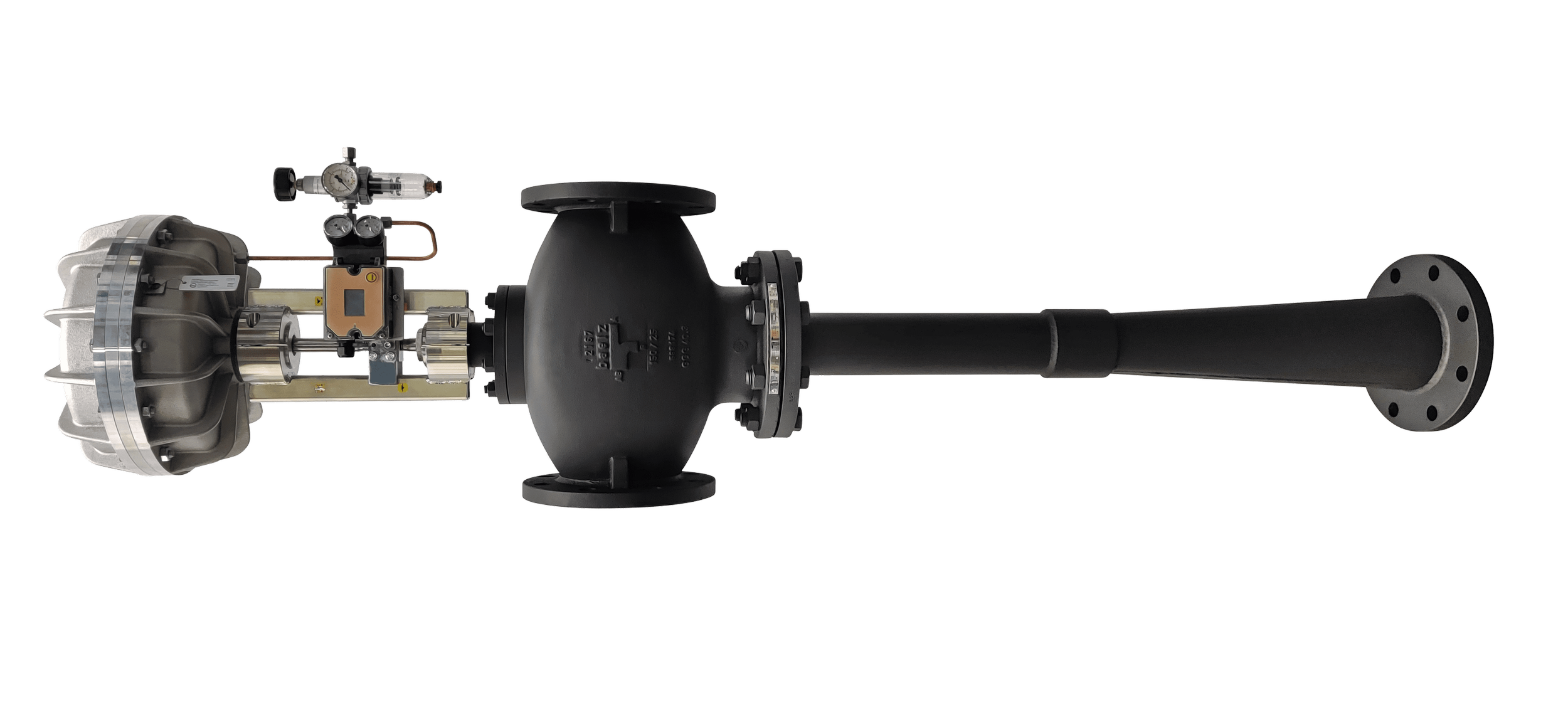
Jetomat Thermocompressor
WHAT IS A CONTROLLABLE NOZZLE EJECTOR (JETOMAT)?
A Jetomat is a Steam Jet Ejector—also called a Steam Thermocompressor, Steam Jet Compressor, or Thermo Vapour Recompressor—with an Adjustable Motive Nozzle. It performs three steps:
Acceleration (Nozzle): High-pressure motive steam expands through a convergent/divergent nozzle (controlled by a spindle/actuator). Pressure energy → kinetic energy (very high jet velocity).
Entrainment (Mixing Chamber): The high-velocity jet creates a low static pressure (vacuum) that entrains the low-pressure suction vapor (often Flash Steam from Steam Condensate return or a process vent). Momentum is transferred from the jet to the suction flow.
Pressure Recovery (Diffuser): The mixed stream enters a Diffuser that converts velocity back into pressure, delivering Mixed Steam to the user at a controlled setpoint.
This is the Steam Jet Ejector Working Principle—a momentum-exchange Vapor Compressor / Steam Compressor that recompresses otherwise wasted vapor.
COMPONENTS OF JETOMAT
A) Operating Modes
Compression Mode (Thermocompression): Raise suction vapor from low pressure to a higher, usable delivery pressure (e.g., suction 1.5–2.5 bar(a), motive 8–12 bar(a), mixed 3–5 bar(a)). This is the classic Heat Recovery System duty.
Recirculation (“back-mix”) Mode: Re-inject a portion of return vapor to increase internal steam velocity across heat surfaces (dryers/hotplates), thinning condensate films and improving Heat Transfer Solutions even when delivery pressure ≈ suction.
B) Main Parts (with control features)
Controllable Motive Nozzle
Geometry: convergent–divergent de Laval.
Actuator + Spindle adjust the effective throat area At, modulating jet mass flow m˙m and Mach number.
Suction Inlet & Mixing Chamber
Admits low-pressure vapor Admits low-pressure vapor; the jet’s shear layer entrains suction flow m˙s.
Length and diameter set for proper momentum transfer and stable mixing over the operating range.
Diffuser (Pressure Recovery)
Converts velocity to pressure; area ratio and contour set compression efficiency and stall margin.
The Diffuser and Nozzle pairing fixes achievable Compression (P Mix / P Suction) for a given Entrainment Ratio (Flow Suction / Flow Motive)
Instrumentation & Controls
Mixed-pressure (or temperature) controller drives the nozzle actuator via a integrated spindle.
Integrates cleanly with plant PLC/DCS for recipe-based control in Heating Systems.
KEY PERFORMANCE QUANTITIES
Entrainment Ratio (Flow Suction / Flow Motive)
Typical for steam service: 0.2–1.5 (design-dependent). Higher ( \omega ) means more recovered vapor per unit motive steam.Compression Ratio (P Mix / P Suction)
With saturated steam and good sizing, 1.3–2.5 is a common practical band for single-stage devices (higher requires multi-stage or elevated motive pressure).Overall Mass Balance
Mixed flow (m4) = Motive Flow + Suction Flow m_m .Energy Implication (rule of thumb)
In compression mode, Each 1 Kg of recovered low-pressure steam typically Displaces ≈1 Kg of fresh boiler steam at the same delivery pressure—driving direct fuel and water/chemical savings.
HOW MODULATION WORKS
A controllable Jetomat adjusts the effective Nozzle area (via spindle/actuator) and/or the motive-steam control valve to keep mixed pressure (or temperature) on setpoint while loads vary.
Example Setpoint Control
Target: Discharge Pressure = 3.0 bar(g) to a dryer section.
Typical operating point: motive = 10 bar(g), suction = 1.8 barg, Entrapment Ratio = 0.7 = 4,800 kg/h.
If heat demand rises (sheet speed up), controller opens the nozzle (or motive valve) to increase Motive; vacuum deepens Suction Flow rises, and Discharge Pressure holds 3.0 bar(g) within ±0.05 bar.
If demand falls, the actuator closes toward minimum; many systems maintain stable Discharge pressure over turndown in motive flow.
Response Time
With a modern actuator and short piping, pressure loop response in <2–5 s is typical—well suited to rapid grade or throughput changes.
WORKED EXAMPLE
Duty: Replace throttling on a heat user with controllable thermocompression.
Motive header: 10 bar(g), saturated (≈180 °C).
Suction source: 2 bar(g) flash steam from a vent/return (≈134 °C).
Required mixed: 3.5 bar(g) (≈152 °C) at 5,000 kg/h total.
Target Design (One Of Many Valid Solutions):
Choose Entrapment Ratio = 0.8 => Suction Flow = 222 kg/h, Motive Flow = 277 kg/h.
Direct Energy Effect: 222 kg/h of low-pressure vapor replaces 222 kg/h of fresh boiler steam.
Fuel Saving Estimate: If 1 t of steam costs Cx(fuel + water + chemicals), annual saving ≈ (0.222 t/h x 8,000h/ x Cx.
Example with ( Cs = ₹2,500/Ton. ₹44 Lacs/Year avoided steam generation.
Scale linearly with your site’s actual steam cost.
WHY IT IMPROVES HEAT TRANSFER
By Entraining vapor and pushing more mass through the user, a Jetomat increases internal steam velocity. That Thins The Condensate film on heat-transfer surfaces (dryers, hotplates, coils), raising effective surface temperature at the same delivery pressure and flattening temperature profiles—directly improving Heat Transfer Solutions and product quality.
BENEFITS
Energy & Utilities
In compression duties, typical mixed-user savings: 10–30% steam demand vs. throttling.
Keeping Steam and Condensate in the loop cuts make-up water and dosing (a built-in Flash Steam Recovery System).
Process Stability & Quality
Tight pressure (or temperature) control → fewer hot/cold spots; better moisture/bond uniformity.
Faster warm-up; higher permitted line speeds.
Maintenance & Reliability
No Rotating Parts in the flow path; minimal wear.
Continuous entrainment often lets you Reduce Trap Counts on controlled sections, simplifying the Condensate and Flash Steam Recovery System.
Integration & Safety
Standard transmitters/valves; easy PLC/DCS integration.
Less venting; in some layouts, reduced reliance on a standalone Steam Separator or flash tank (site standards apply).
Where It Fits
Textile cylinder dryers/stenters; Paper/Corrugated dryers, preheaters, hotplates; Food & Beverage evaporators/reboilers.
Any throttled user with a nearby low-pressure vapor source.
PRACTICAL DESIGN & COMMISSIONING NOTES
Data You Need: Motive header pressure/temperature, suction source P/T and flow or vent rate, required mixed setpoint, allowable pressure drops, load profile.
Sizing Targets: Choose Entrapment Ratio and Compression within feasible map; check nozzle critical flow and diffuser margin to avoid stall at extremes.
Piping: Keep suction short/clean (large radius, minimal fittings); insulate; ensure proper drainage to avoid liquid carry-over.
Controls: Start with mixed-pressure control; for critical quality, use surface-temperature feedback.
Turndown: Aim for suitable motive turndown in controllable nozzles; validate stability on both high/low ends.
Commissioning: Trend all flows, valve position, and product KPIs; verify that recovered vapor indeed reduces boiler feed and vent flows.
CONCLUSION
A Jetomat controllable nozzle ejector is a precise, durable way to turn wasted pressure and vapor into stable useful steam. By modulating the motive Nozzle (via spindle/actuator) and recovering Flash Steam in a well-matched Diffuser, it functions as an in-line Thermo Compressor—cutting fuel, simplifying hardware, and improving heat transfer.
How to Proceed
Identify one throttled user with a nearby low-pressure vapor source.
Gather real pressures/flows and define the mixed-steam setpoint.
Request a Thermocompressor Design check.
Pilot the controllable ejector; baseline and then measure steam, water/chemicals, and quality KPIs for 2–4 weeks.
Scale to other users and formalize a sitewide Heat Recovery System approach.