
Uniform Roll Heating on Paper Calenders
INTRODUCTION
Calenders make paper smooth, glossy, and consistent—but only if the calender rolls stay at a uniform surface temperature around the full circumference and across the face width. Traditional setups use Control Valves and Steam Traps inside the steam-heated rolls. At low loads or rapid speed/grade changes, condensate can pool, traps cycle, and temperatures wander—showing up as gloss bands and thickness variation.
A smarter approach is to install a Jetomat Steam Jet Ejector on the calender’s steam circuit to circulate steam and actively pull Condensate/Flash through the roll. You get steady temperature, Saving Energy, and a calmer, simpler loop.
WHAT IS THE JETOMAT APPROACH
A Jetomat is a controllable Steam Jet Ejector / Steam Jet Compressor. High-pressure motive steam expands through a shaped Nozzle, creating a vacuum that Entrains low-pressure vapor from the roll’s outlet. In the Diffuser, velocity is converted back to pressure, delivering Mixed Steam at the setpoint to the roll inlet.
This is the classic Steam Jet Ejector Working Principle—a momentum-exchange Vapor Compressor / Steam Compressor with no rotating parts. In calender service, it becomes a built-in Condensate and Flash Steam Recovery System that keeps the roll internals swept and hot.
COMPONENTS OF THE CALENDER CIRCUIT
Controllable Motive Nozzle (with Actuator)
Pneumatic or electric actuator moves a spindle to modulate the nozzle throat area.
Typical controllable turndown 3:1–5:1, fast response (≈2–5 s)—ideal for speed/grade steps.
Mixing Chamber + Diffuser and Nozzle
The jet Entrains the roll outlet stream (steam + Steam Condensate flash).
The Diffuser rebuilds pressure to the roll’s mixed-steam setpoint.
Roll internals & headers
Supply (mixed) pressure: often 2.5–4.0 bar(g) (Tsat ≈ 135–152 °C), per calender design.
Outlet (suction): near atmospheric to 0.5 bar(g); short, well-drained pipe to the ejector suction.
Instrumentation & Controls
Primary Loop: mixed-steam Pressure (or roll shell Temperature) → actuator setpoint.
Optional: surface IR sensors (MD/CD), suction pressure, and calender exit moisture/gloss for diagnostics.
A small upstream Steam Separator is optional if the motive line is wet.
TEMPERATURE NON-UNIFORMITY SOLVED
Inside a steam-heated roll, the main enemy is a Thick Condensate Film on the inner surface. It insulates the shell, lowering local heat flux. When traps cycle, parts of the shell cool and re-heat, causing circumferential/axial hot–cold bands.
What the Jetomat Changes
Continuous Circulation raises internal steam velocity → Thinner Condensate Film → higher, more uniform heat flux.
Active Suction evacuates condensate quickly at all positions—no water-logging at the bottom sector.
Stable Setpoint: the ejector holds mixed pressure within ±0.05 bar, keeping shell temperature within ±1–2 K when tuned.
Representative Results (field-typical ranges):
Surface temperature spread (circumference): ±5–7 K → ±1–2 K.
Face-width temperature taper: >4 K → ≤1.5 K with balancing orifices.
Gloss standard deviation: −20–35%.
Caliper 2-σ variation: −10–20% (grade-dependent).
Steam use: −10–15% on the calender section when previously throttled/vented.
(Your exact numbers depend on roll size, internals, and insulation.)
EXAMPLE — 8m Face Calender Roll
Roll Size: Ø 1.2 m, face 8.0 m
Target Shell Temperature: 150 °C (≈ 3.4 bar(g) saturated)
Baseline (valve+trap):
U ≈ 650 W/m²·K; ΔT eff ≈ 30 K
⇒ Heat flux ( q = U\Delta T ) ≈ 19.5 kW/m²With Jetomat Circulation: U ↑ +20–30% (thinner film) → say 800–850 W/m²·K
⇒ ( q ) ≈ 24–25.5 kW/m² (+25–31% local heat rate)
Impact: either reach temperature faster after grade/speed increases, or run the same line speed with Less Motive Steam. Because the ejector reuses Flash Steam from the outlet, each 1 kg of recovered vapor typically displaces ≈1 kg of fresh steam at the same pressure—direct Saving Energy.
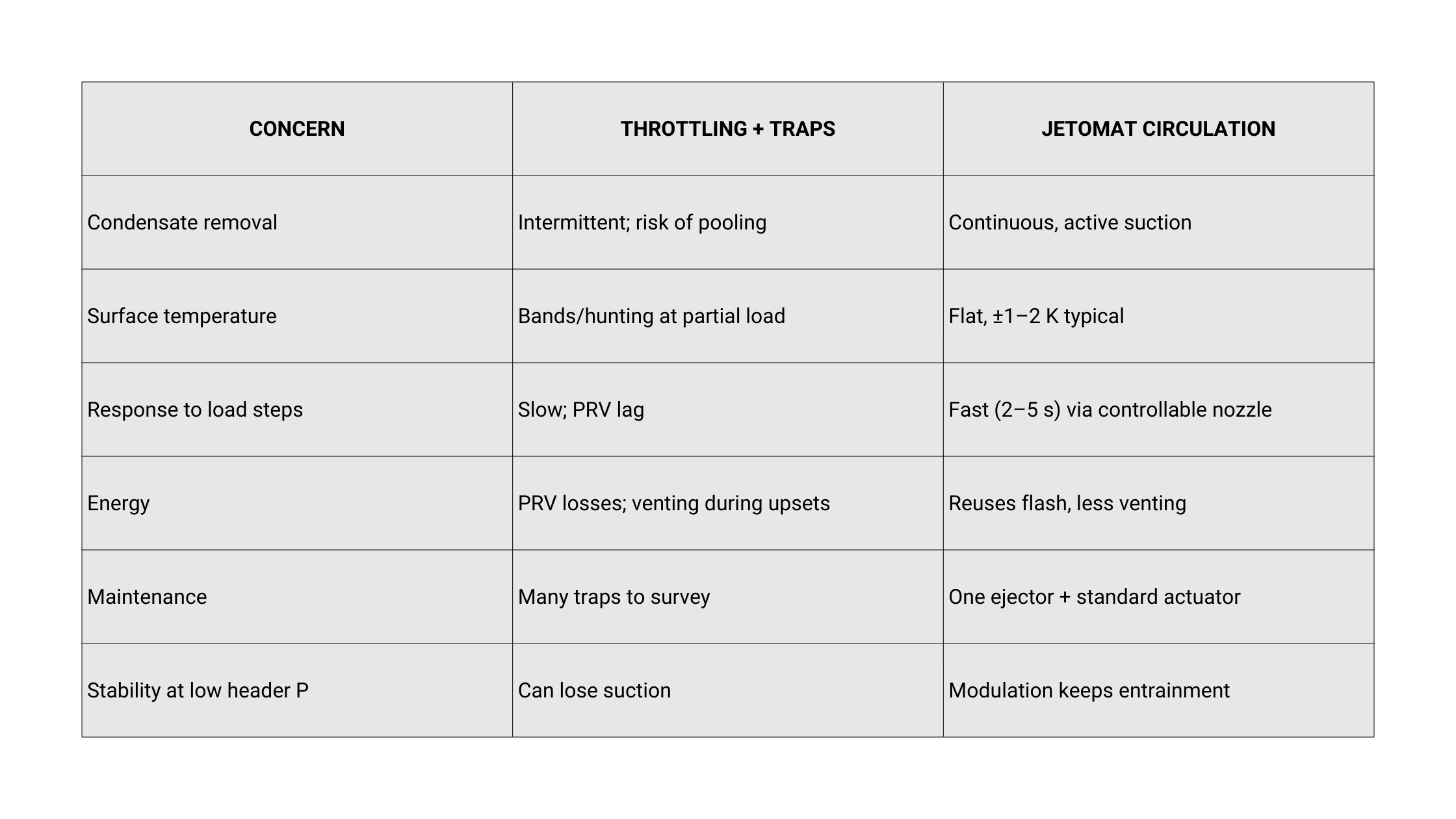
WHY A JETOMAT BEATS THROTTLING + TRAPS
CONTROL PHILOSOPHY
Mixed-pressure control: hold, e.g., 3.2 bar(g) to match the grade recipe; add gentle ramp limits to avoid overshoot on light grades.
Feed-forward: bias the setpoint or controller output with paper speed and MD load changes.
Balancing along the face: use small orifices/manual valves to even flow between sectors; the ejector handles the heavy lifting.
Turndown: specify 3:1–5:1 motive turndown so low-speed operation remains stable.
BENEFITS
Quality & Runnability
Even shell temperature → even gloss and caliper; fewer bands and rejects.
Faster heat-up after grade/speed changes → less off-spec tonnage.
Energy & Utilities
Heat Recovery System: outlet Flash Steam re-entrained and reused; less PRV throttling and venting.
Lower Make-up Water and dosing as more Steam and Condensate stay in-loop.
Reliability
No Rotating Parts in the process path; fewer small traps and bypasses.
Quieter operation (vents closed), lower water-hammer risk.
Simplicity
Compact piping; standard PLC/DCS control; optional Steam Separator only if an instrument demands ultra-dry steam.
Practical Design Notes
Data to Size: motive header P/T, target mixed pressure/temperature, expected outlet (suction) P/T, roll internal geometry, pressure drops.
Piping: keep suction short, insulated, and pocket-free; slope for drainage; use large-radius bends to protect entrainment.
Actuation: choose pneumatic (fast, spring fail-safe) for highly dynamic loops or electric (digital integration) for steady loops.
Commissioning KPIs: mixed pressure stability (±0.05 bar), circumferential and CD surface temperature (IR trending), gloss SD, caliper 2-σ, steam/ton on calender section.
Conclusion
Calender quality lives and dies with uniform roll heating. A Jetomat Steam Jet Thermocompressor turns the calender’s steam circuit into a Circulating Loop that keeps the shell uniformly hot, adapts instantly to load changes, and Saves Energy by reusing Flash Steam. Plants report tighter gloss/caliper, fewer bands, and lower fuel—without adding complex machinery.
How to proceed
Log a week of calender data: shell temperatures (MD/CD), steam pressures, speed/grade changes, and steam/ton.
Request a Thermocompressor Design check (entrainment ratio, compression ratio, Nozzle Design, actuator choice).
Pilot on one roll; track temperature flatness, energy, and quality for 2–4 weeks.
Scale to other rolls or pairs once the data confirms stability and savings.