The Science of Thermocompression Explained
How a Jetomat thermocompressor recovers flash steam and cuts steam use by up to 30% (Baelz cases: 15–32%). See the working principle, in India.
On this page
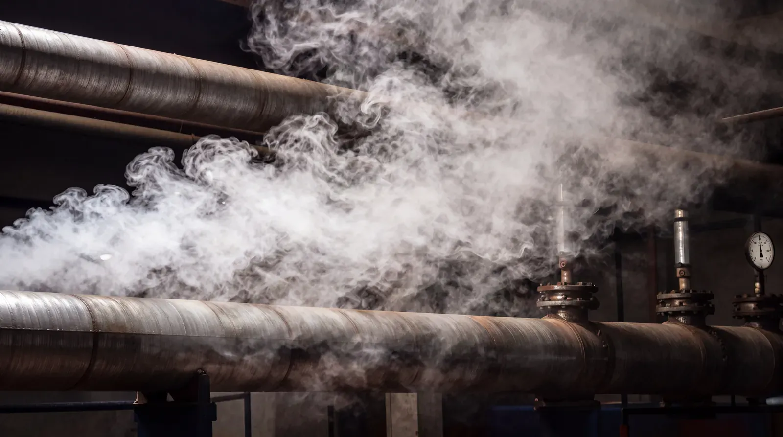
Most plants still reduce steam pressure with a valve & dump flash steam through traps or vents. That’s simple—but wasteful. The idea behind thermocompression is even simpler: don’t throttle—recycle. Use a small amount of high-pressure steam to pull in low-pressure vapour/flash & re-pressurise it back to a useful level. The result is steadier heating, better heat transfer, & energy savings—often in the double digits.
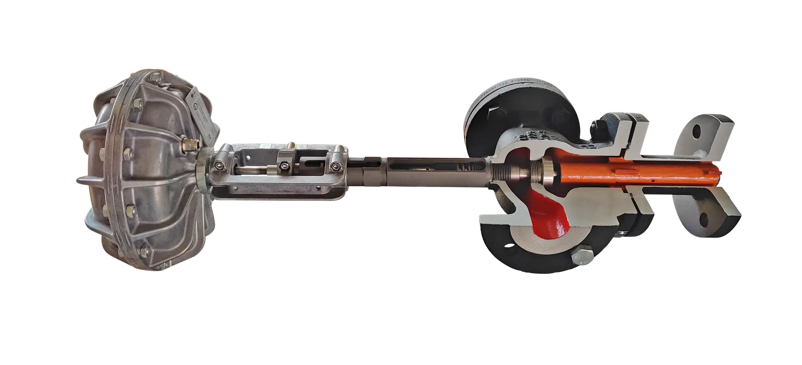
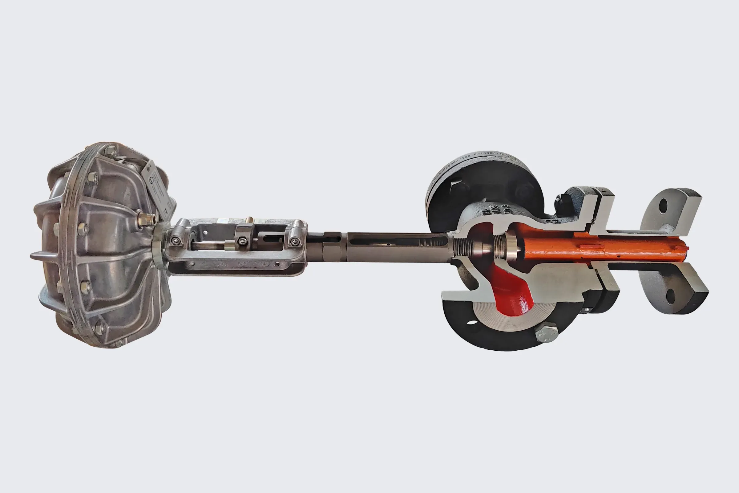
Thermocompressor
What is Thermocompression?
Thermocompression uses a jet device to mix two steam streams of different pressures:
Motive steam (from the boiler header) at higher pressure.
Suction steam at lower pressure (typically flash steam from condensate, vapour from a process vessel, or return from a dryer/heat user).
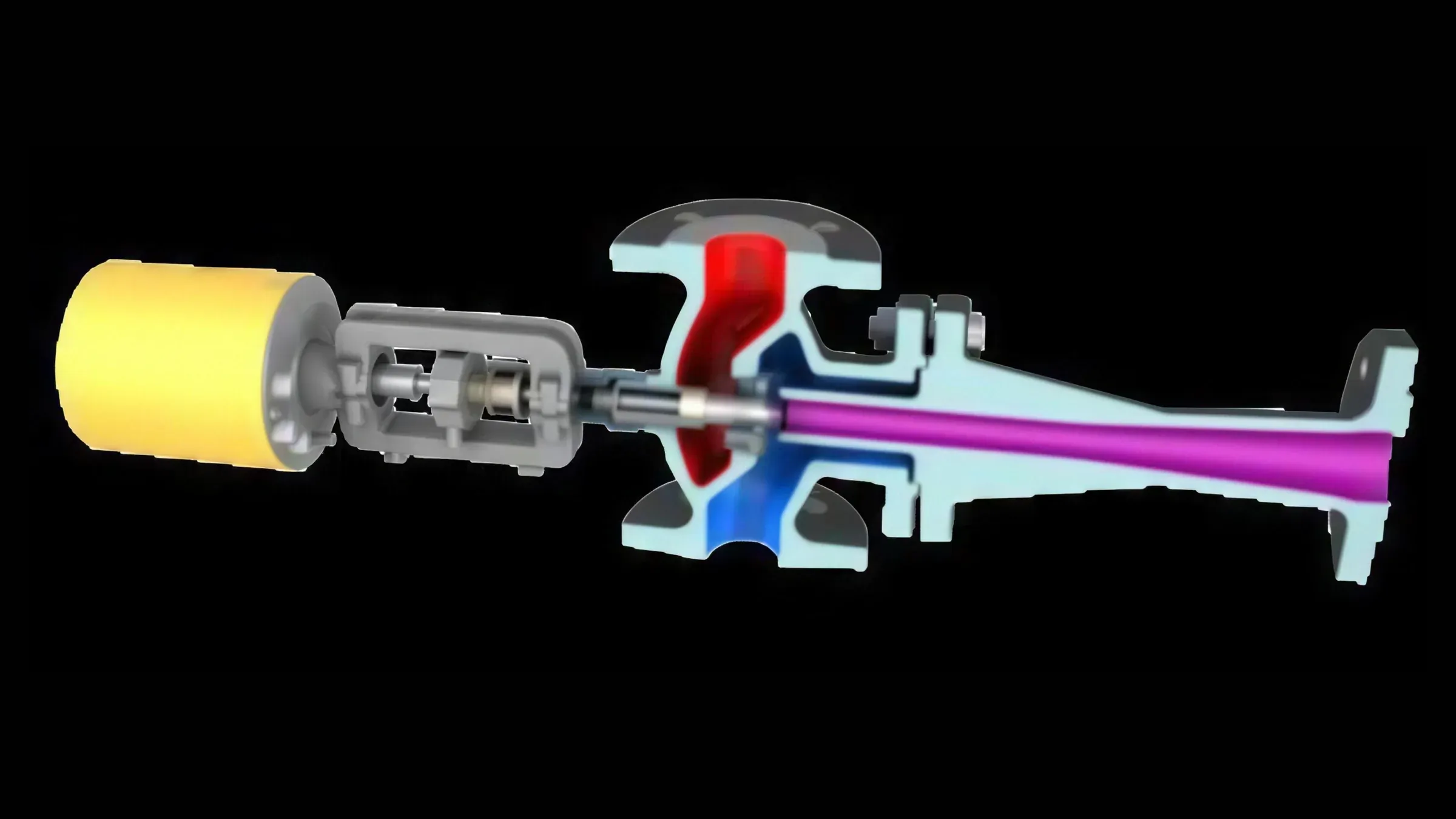
Inside the ejector, the motive jet entrains the low-pressure vapour & the pair exits as mixed steam at an intermediate, controlled pressure useful to the process. This is how a steam jet ejector works—& it’s the reason a Jetomat thermocompressor can act like a compact, robust vapour compressor.
Components of a Jetomat System
OPERATING MODES
Recirculation / Back-mixing mode
Goal: improve heat transfer by raising internal steam velocity & sweeping condensate films.
Benefit: faster warm-up, more uniform surface temperature, better dryer/heat-exchanger performance.
Compression mode
Goal: recover heat—capture low-pressure flash/vapour & re-pressurise it to the user setpoint.
Benefit: displaces fresh boiler steam, enabling substantial energy savings & reducing make-up water & treatment chemicals.
HOW IT WORKS
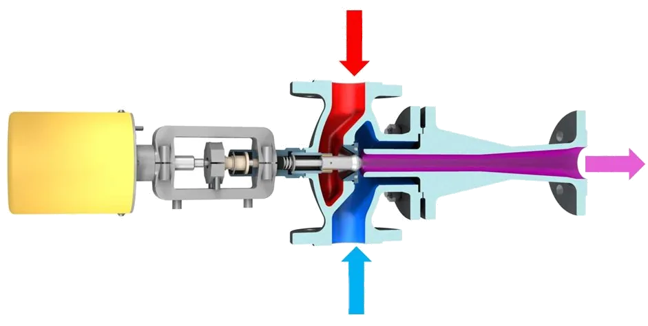
Jetomat Working
Motive steam acceleration
High-pressure steam flows across the variable motive nozzle, trading pressure for velocity. Think of this as creating a high-speed jet.Entrainment of suction vapour
That jet lowers static pressure in the suction chamber, pulling in low-pressure flash steam (& any compatible vapour). This is the “recycling” step.Mixing & momentum transfer
In the mixing section, the fast jet shares momentum with the suction vapour. Energetically, a portion of the motive steam’s exergy is transferred to the low-pressure vapour.Pressure recovery in the diffuser
The diffuser slows the mixed flow, converting velocity back into pressure to your setpoint. That mixed steam goes to the user—dryers, coils, calenders, reboilers—as a controlled supply.
KEY PERFORMANCE TERMS
Entrainment ratio (ω) = suction flow / motive flow.
Compression ratio = (mixed-steam pressure)/(suction pressure).
Turndown = controllable operating range via motive-steam valve position.
SYSTEM ACCESSORIES
Instrumentation & control: pneumatic or electric actuator for the variable nozzle, mixed-pressure PID / PLC controller, temperature feedback, flow/pressure transmitters.
Piping good practices: strainers on motive line, short suction runs, gentle reducers to avoid pressure drop.
Condensate handling: many thermocompressor layouts simplify or remove trap banks by recovering the condensate & flash steam.
Steam separator / flash vessel (as needed): depends on site standards; often reduced or streamlined because the ejector itself recovers the flash steam.
Benefits & Applications
1) Energy, Throughput, & Quality
Recover instead of venting: the Jetomat reuses flash steam that PRVs & traps usually waste. Plants frequently document 10–30% steam reductions in compression service.
Better heat transfer: higher internal steam velocity thins the condensate film, raising effective surface temperature & improving uniformity. Many users see faster warm-up & higher line speeds.
Stable conditions: the mixed-steam pressure is controlled; fewer hot/cold spots, less cycling, & more consistent product quality.
2) Less Hardware, Fewer Headaches
Simplified loops: a well-designed thermocompressor can replace PRVs + multiple traps + vent lines. In some dryer sections, trap counts drop drastically or disappear.
3) Where It Fits in the Process Industries
Dryers / cylinders / can-dryers (paper, textile): raise velocity, sweep condensate, reclaim return steam.
Evaporators / concentrators (food & beverage, chemicals): recompress secondary vapour
Reboilers, cookers, sterilisers: recycle overhead vapour to reduce fresh steam draw.
General steam equipment retrofit: anywhere a PRV drops pressure & a vent or trap wastes vapour.
4) Typical Numbers (What to Expect)
Energy: double-digit % steam savings are common where flash losses exist.
Water/chemicals: reduced make-up & dosing by keeping steam & condensate in the circuit.
Maintenance: fewer traps & valves to survey; the ejector itself is largely maintenance-light.
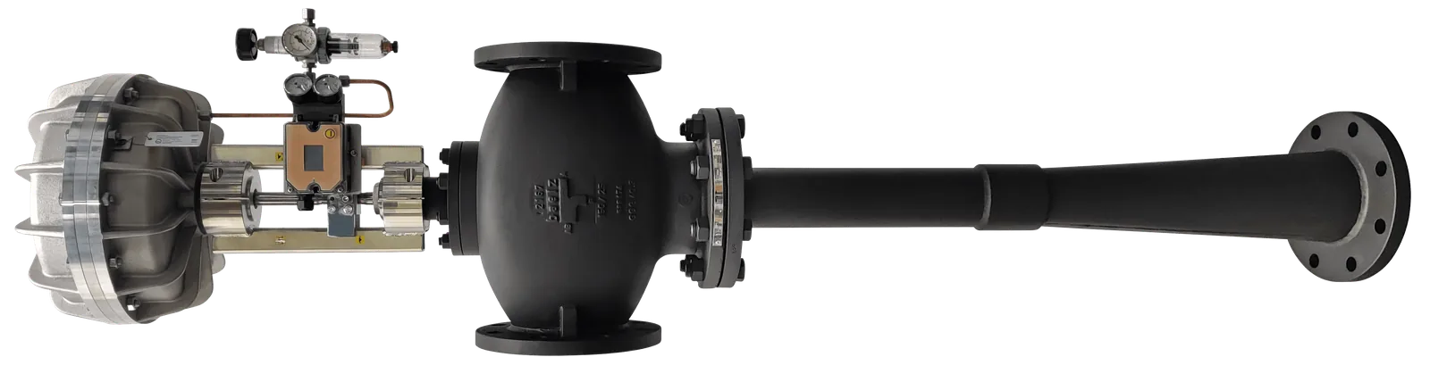
Jetomat
How the Variable Nozzle Holds Pressure
A Jetomat moves the spindle in its variable motive nozzle (pneumatic or electric actuator) to keep the mixed-steam pressure, or temperature, on setpoint while the load moves.
Example: target discharge 3.0 bar g to a dryer section; motive 10 bar g, suction 1.8 bar g, entrainment ratio 0.7, mixed flow ≈ 4,800 kg/h.
Load rises (sheet speed up): the controller opens the nozzle, motive flow rises, suction deepens, more flash steam is drawn in & the discharge pressure holds.
Load falls: the spindle closes towards minimum & the discharge stays stable across the turndown.
A fixed-nozzle ejector works at one design point only. More in Controllable vs. Fixed Ejectors.
Practical Design Notes
Data first: collect motive header pressure/temperature, suction source pressure, current vent/flash locations, target mixed pressure/temperature, & expected load swings.
Right-size the ejector: match the thermocompressor design to real operating points; avoid chronic blow-off or starving.
Control philosophy: most plants regulate by mixed-steam pressure; others use temperature (e.g., drum shell or condensate outlet).
Layout details: short, open suction; avoid long, restrictive runs. Install strainers on motive line. Provide proper condensate drainage.
Integration: the Jetomat drops in ahead of the user, replacing PRVs. Existing DCS/PLC handles the motive-valve loop; no special black-box control required.
Conclusion
Thermocompression is simply smarter steam use. A Jetomat steam jet ejector functions like a durable steam compressor, built from a nozzle & diffuser, to recycle flash steam & stabilise your heating. The results are predictable: energy savings, cleaner loops with fewer traps, & better heat transfer.
What to do next
Screen your sites: where do you throttle with a PRV & see vent plumes or heavy trap maintenance?
Quantify: build a quick mass/energy balance on motive vs suction flows; size a thermocompressor to your target mixed pressure.
Pilot & prove: convert one throttled user (dryer, evaporator, reboiler), measure steam, temperature stability, & product KPIs.
Scale up: standardise the design across similar units to lock in plant-wide benefits.
Already running a Jetomat that has lost performance? We repair & restore Jetomat units in Pune.
If you’d like help with a quick review of your steam recovery—or to see how a Jetomat could fit your loop—reach out for a no-obligation assessment. We’ll map the thermocompressor principle to your process & deliver a practical, measurable plan to modernise your steam network.
Get More In-Depth Science